Navigation
The JABLOTRON 100+ security system enables the PG and electric valve to shut off the water supply with open-close logic, thus increasing the security of the building. The advantage of this type of valve is also an emergency condition for permanent closing with the possibility of remote/manual unblocking. Another available function is the option of delayed valve closure, for example to complete the processes of household appliances.
THE VALVE CAN BE CONTROLLED BY THE USER


NECESSARY EQUIPMENT

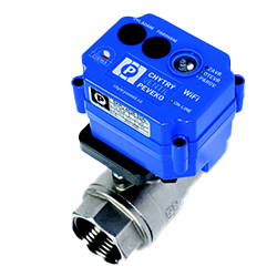
SKPB 4015.2RKX/J0J6
SKPB 4020.2RKX/J0J6
SKPB 4025.2RKX/J0J6
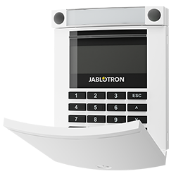
access module
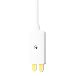
Wirelles flood detector
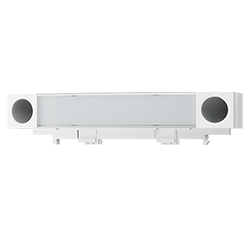
Control segment for access modules
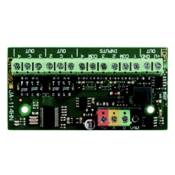
Bus four-input and four-output module
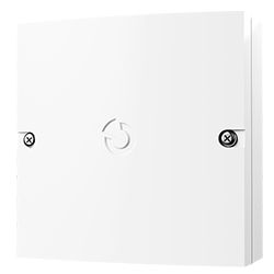
Multipurpse installation box
WIRING

Wiring requires knowledge of the manuals of all components used. The current documents can be found on MySTORAGE.
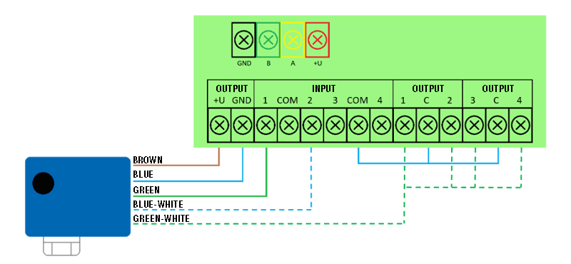
The figure below shows a schematic of an example of connecting the valve drive unit to the JA-114HN module.
- The circuit uses a 4 input and 4 output PG bus module to control and monitor the status of the valve.
- • The valve responds to a pulse shorter than 2 s (opening/closing), in case of a longer pulse than 3 s it is an emergency condition that is permanent until unblocking, which is achieved by a pulse of 4 s. If you need to enable/disable delayed closure, you need to select one of the following pulse lengths.
- Pulse length 7 s – delayed closure 1 h
- Pulse length 9 s – delayed closure 2 h
- Pulse length 11 s – delayed closure 3 h
- Pulse length 13 s – delayed closure 4 h
- • Valve wiring description: brown wire – 12 V, blue wire – GND, green wire – valve status, blue/white wire – valve disconnection (sabotage function), green/white wire – control.
SETUP AND PROGRAMMING

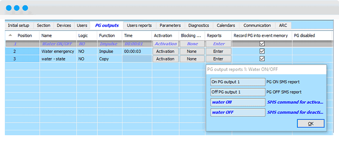
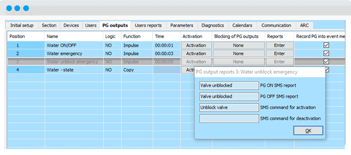
1. In F-Link, on the PG Outputs page, set the behavior of the three PG outputs. The first will generate a 2s pulse for standard valve control. The second one with a 3s pulse for an emergency condition reacting to a flood in the building. The third PG is for 5s impulse for unblocking emergency state. We will use the fourth PG to monitor the valve status using the JA-114HN input and then display it on the keypad segment. The fifth PG is used when a delayed valve closure is required. Select the delay time as required, see the explanation in the element wiring.

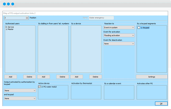
2. For the JA-114HN 4-input and 4-output bus module, set the corresponding PG and input behaviour.
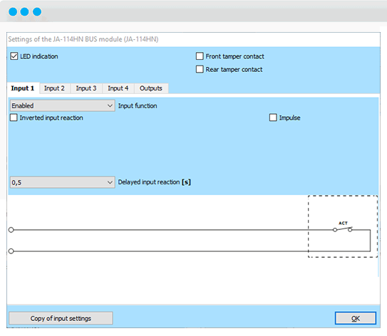
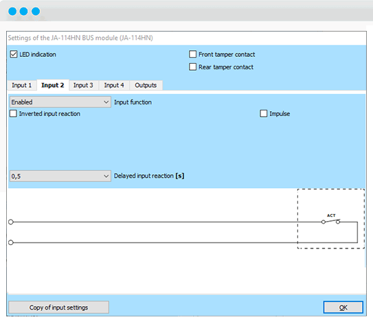
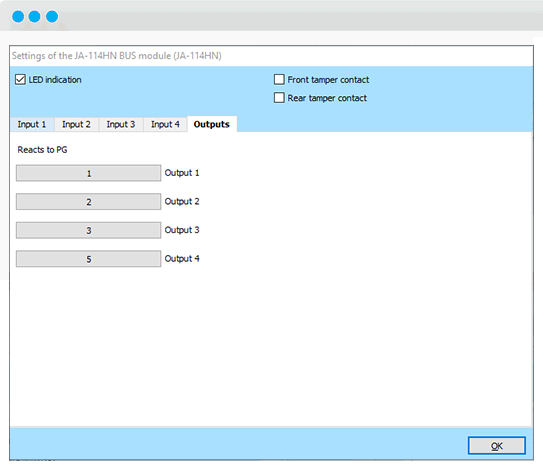
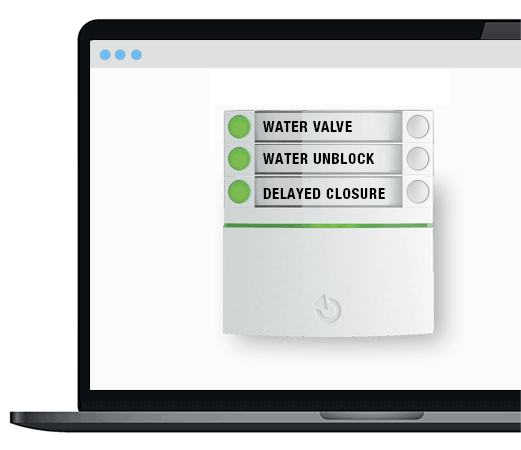
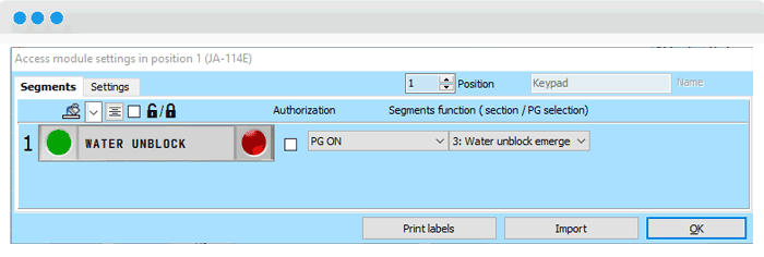
3. To set up the control and indicator segments on the keyboard, you need to open the internal settings on the Devices tab using the Enter button. For the respective segment, select the PG output and assign it the control function “PG indicates/controls”. In this case, we indicate PG3 (Water Status) and control PG1 (Water ON/OFF).

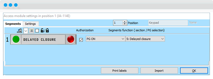
Set the segment for controlling the PG1 output with on and off and authorization selection. When authorization is required, authorized users will need to set permissions to control PG1 in the Users tab. It is also possible to create a segment for unblocking with PG3 (Water Emergency Unblocking) and assign this option only to authorized users. If you need to use delayed start, you can create a segment for delayed closure. If it is pressed, the 2 s pulse for valve on/off is not responded to at all times.
LOCAL AND REMOTE CONTROL

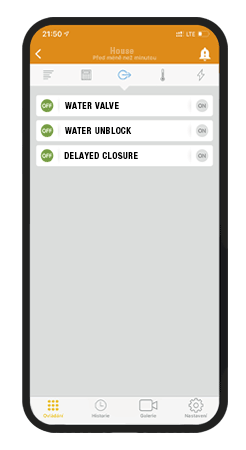
The water shut-off can be controlled both locally from the keypad segment and remotely outside the building. For the remote method, the MyJABLOTRON web or mobile app can be used by clicking on the virtual segment or SMS command with a configurable text.
